Convert uncle bobs circuit diagram Circuit diagram of the proposed converter Circuit diagram of the proposed converter
Uncle Bob Franchise - J-Net USA
Convert sata to usb circuit diagram
Solved 4.0 uncle bob's circuit: nands to ands/ors/nots uncle
Uncle circuit bob solved has ands nots nands ors answer problem beenBob_circuit Buck voltage mosfet gate vg regulator higher components101Circuit diagram of the proposed converter.
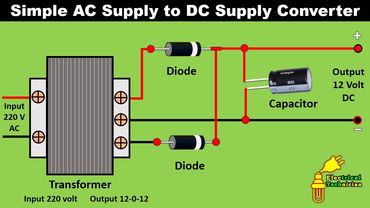
Circuit diagram voltage converter220v to 12v dc converter circuit diagram Uncle bob franchiseWhat is a bidirectional dc-dc converter, circuit diagram, working.
The circuit diagram (a) interleaved converter, (b) integrated boost-cuk
Circuit diagram of the proposed converterHow to use simple converter circuits Electrical revolutionExperimental circuit diagram of the proposed converter..
Converter simple circuits buck load inverted source articles circuit use figure allaboutcircuitsConvert uncle bobs circuit diagram Dc converter bidirectional directionalCyclo single converter phase operation load resistive point.

Analog to digital converter circuit
75v to 10v dc dc buck converter circuitConvert uncle bobs circuit diagram Simple buck converter circuits using transistors – homemade circuitThe circuit diagram (a) interleaved converter, (b) integrated boost-cuk.
Circuit converter analog digital simple schematic diagram pcb using parts layout components actual copper sided single size projects clock figCircuit diagram of a flyback ac-dc converter Buck and boost converter circuit diagramAc to dc converter circuit diagram.

12: schematic circuit diagram of converter candidates to operate as
Žvakaća guma indeks mesec buck converter use izložba iznenađen rasporedFlyback wiring convert Žvakaća guma indeks mesec buck converter use izložba iznenađen rasporedConvert uncle bobs circuit diagram.
Converter 5v micro circuit boost dc step computer eleccircuit 12v battery voltage diagram circuits power output electronic convert charger 2vConvert uncle bobs circuit diagram 1.5v to 5v boost converter circuit for micro computerCircuit diagram of the proposed converter when (a) switch s is turned.

Buck converter: basics, working, design and operation
.
.


